Loading...
PRODUCTS
ACCESSORIES
Having pushed ahead with quality improvement, Koryo Nobel Explosives is now orientated towards the global market.
Electric Detonator(KONEL-E)

Performance
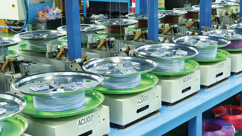
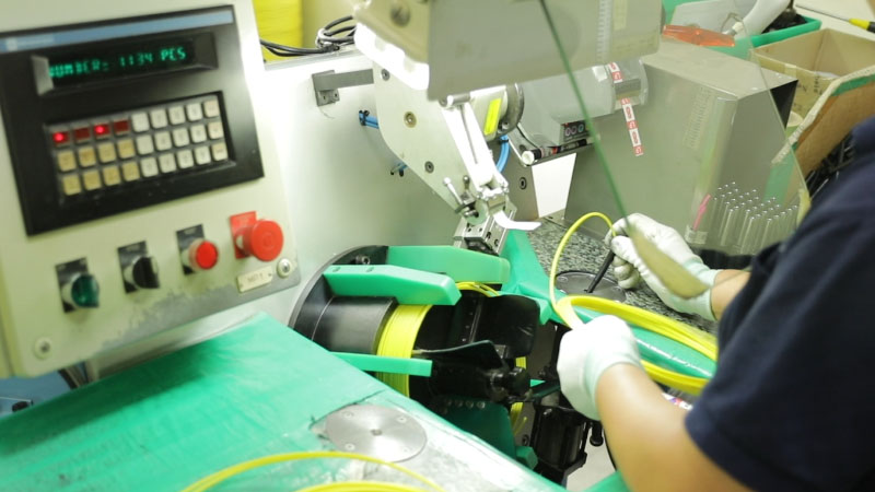
The electric detonator is a No. 8 detonator that employs the NPED method, and is the safest electric detonator in the world, with excellent detonation power. As each component of the detonator exhibits static electricity resistance, stability against static electricity has been improved. Since high ignition energy is required, it has outstanding stability against leakage currents and tray currents, and since the detonator packing paper also exhibits static electricity resistance, safety is the top priority.The interval for each stepped pulley is 25ms, which has been determined to represent the ideal interval for stepped pulleys via the extensive experience of numerous experts worldwide. For the detonator leg wire, the wire connection operation has been made more convenient by improving hangup through an 8-shaped wire winding through an automatic wire winder, and the detonator capsule has been triple-clipped to boast outstanding water resistance.
Pipe section

Blasting system

Instantaneous Detonators
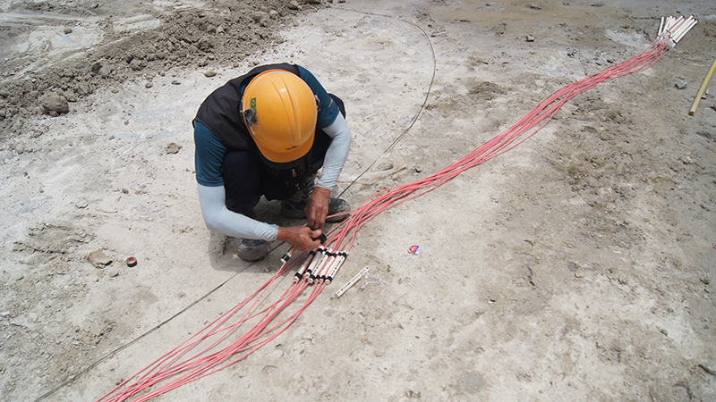
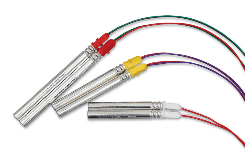
This is a detonator without delay elements inside, making for an electric detonator without any time lag, as detonation occurs at the moment the electric current flows into the leg wire.
*Sleeve color : white
*Sleeve color : white

MS Detonators
(Milli Second Delay Detonators)
This is composed of 2~20 stages. Since the time difference interval for each stage is a short and precise time interval of 25ms, it is effective for ensuring uniform friability, flying stone control, and control of blasting and noise.
*Sleeve color : yellow
*Sleeve color : yellow
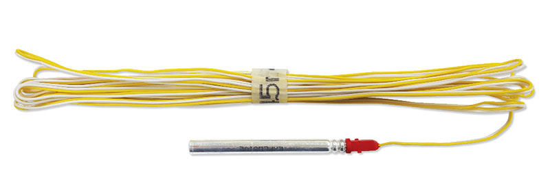
LP Detonators
(Long Period Delay Detonators)
This is composed of 2~20 stages. Since the time difference interval for each stage is a relatively long time interval of 100~500ms, it can be used effectively for blasting underground spaces such as shafts or tunnels.
*Sleeve color : red
*Sleeve color : red
Delay time specification
MS
| Step | Delay time(ms) | Color of Leg wire | |
| Supersensitive | 0 | white | red |
| 2 | 25 | 백 | blue |
| 3 | 50 | white | purple |
| 4 | 75 | white | green |
| 5 | 100 | white | yellow |
| 6 | 125 | white | black |
| 7 | 150 | red | blue |
| 8 | 175 | red | purple |
| 9 | 200 | red | green |
| 10 | 225 | red | yellow |
| 11 | 250 | white | red |
| 12 | 275 | white | blue |
| 13 | 300 | white | purple |
| 14 | 325 | white | green |
| 15 | 350 | white | yellow |
| 16 | 375 | white | black |
| 17 | 400 | red | blue |
| 18 | 425 | red | purple |
| 19 | 450 | red | green |
| 20 | 475 | red | yellow |
LP
| Step | Delay time(ms) | Color of Leg wire | |
| - | - | - | |
| 2 | 500 | white | blue |
| 3 | 600 | white | purple |
| 4 | 700 | white | green |
| 5 | 800 | white | yellow |
| 6 | 900 | white | black |
| 7 | 1000 | red | blue |
| 8 | 1200 | red | purple |
| 9 | 1400 | red | green |
| 10 | 1600 | red | yellow |
| 11 | 1800 | white | red |
| 12 | 2000 | white | blue |
| 13 | 2500 | white | purple |
| 14 | 3000 | white | green |
| 15 | 3500 | white | yellow |
| 16 | 4000 | white | black |
| 17 | 4500 | red | blue |
| 18 | 5000 | red | purple |
| 19 | 5500 | red | green |
| 20 | 6000 | red | yellow |
Average resistance per Leg wire length
| Leg wire length(m) | 1Resistance per 1(Ω) ± 0.3 |
| 2.5 | 1.05 |
| 3.5 | 1.20 |
| 4.5 | 1.35 |
| 6 | 1.65 |
| 8 | 2.00 |
| 12 | 2.70 |
Ignition current
| Connection method | Standard ignition current(Amp) | |
| DC | 1 | 1.5 |
| 50 | 4.5 | |
| 100 | 6.75 | |
| 200 | 9.75 | |
| AC /DC(Based on 50 series) | 4.5 Amp | |
Packing standard
| Length(m) | Packing quantity | ||
| quantity / static electricity bag | quantity / BOX | quantity / BOX | |
| 2.5 | 10 | 20 | 200 |
| 3.5 | 10 | 20 | 200 |
| 4.5 | 10 | 20 | 200 |
| 6.0 | 10 | 20 | 200 |
| 8.0 | 10 | 10 | 100 |
| 12.0 | 10 | 10 | 100 |
Non-electric detonator-Nonel
Performance
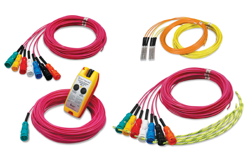
For the first time domestically, a non-electric detonator system has been incorporated, produced via the excellent quality and safety of Dyno Nobel—the first company to develop a non-electric detonator. The NPED Nonel detonator boasts precision for accurate delay times and is excellent safety to prevent electrical risks.The non-electric detonator contains a minor amount of the explosive (HMX) inside the plastic tube, detonating the detonator by transmitting shockwaves at an explosion velocity of 2,000m/sec to the inside of the plastic tube. The non-electric detonator tube is not detonated via a blow or other mechanical action, or even combustion of the tube, and is very strong against any external impact due to its triple structure. Additionally, delay times are displayed on the capsule surface, and the tube colors were made to be easily identified by classification per product (MS, LP, surface detonator).
Pipe section

Blasting system
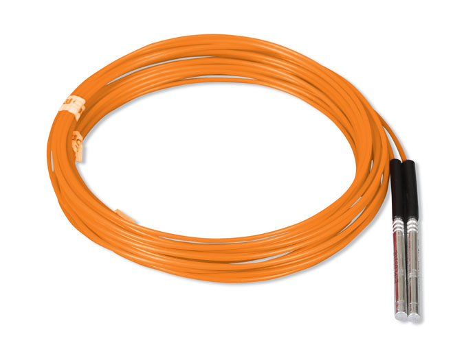
MS Delay Detonators
(Milli Second Delay Detonators)
This is composed of 2~20 stages. Since time difference interval for each stage is a short and precise time interval of 25ms, it is effective for ensuring uniform friability, flying stone control, and control of blasting and noise.
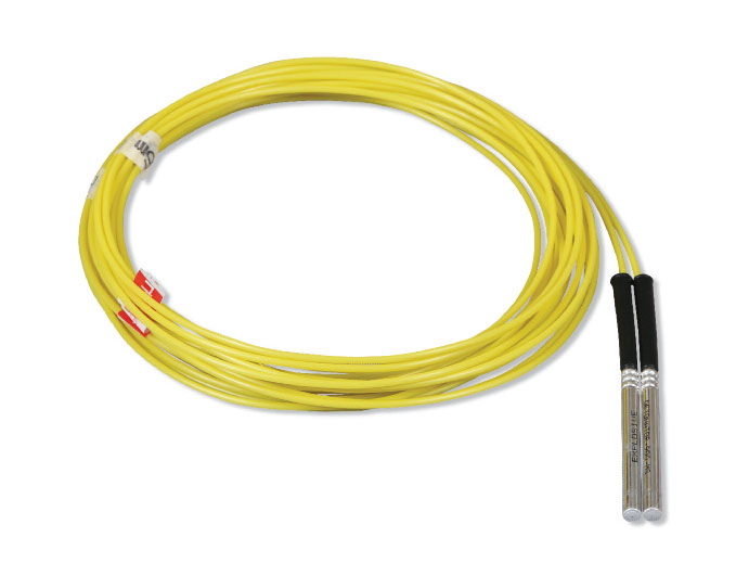
LP Detonators
(Long Period Delay Detonators)
This is composed of 0~60 stages. Since time difference interval for each stage is a relatively long time interval of 25~500ms, it can be used effectively for blasting of underground spaces such as shafts or tunnels.
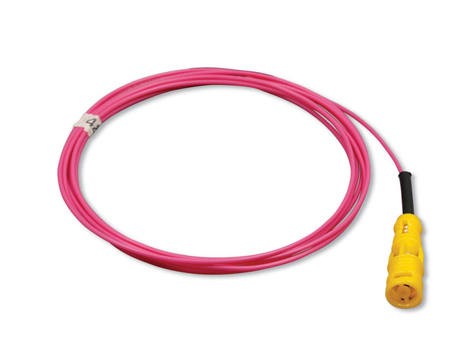
Unidet Block
By connecting a maximum of 8 tubes to the block combined with the detonator, detonation can occur, and a stepped pulley can be applied in a diversified manner by utilizing a range of delay times (7 types).
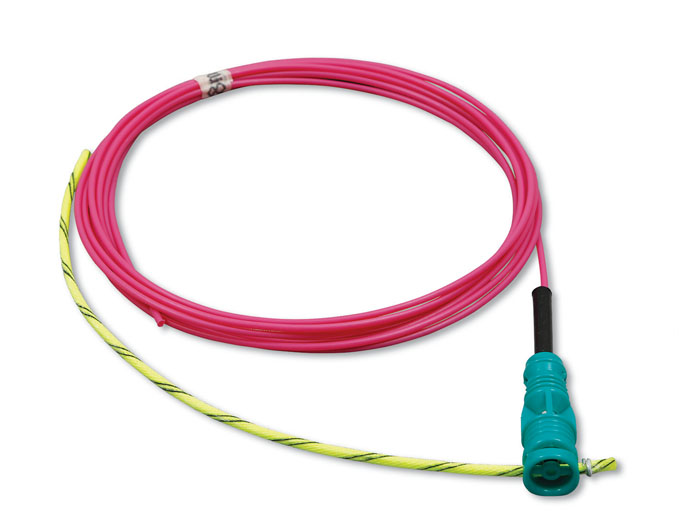
Bunch Connector
By connecting 20 tubes to the detonation fuse at a time, detonation can occur, and a stepped pulley can be applied in a diversified manner by utilizing a range of delay times (7 types).

Starter
This is a detonator for detonation capable of igniting a non-electric blasting system, and allows for supply in diversified lengths to enable safe detonation from a remote distance.
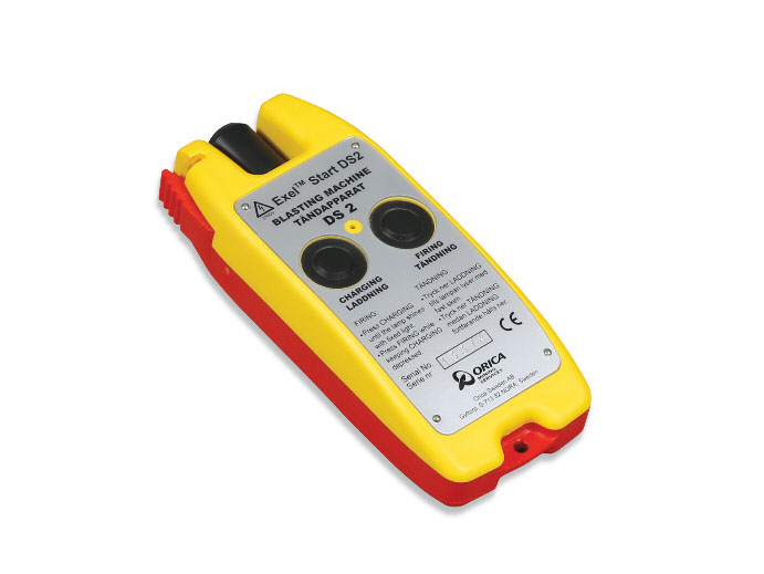
Non-electric detonator blasting machine
This is a dedicated blasting machine that enables safe and convenient detonation of a non-electric blasting system, and has designed for mounted tube cutting for convenient use.
Delay time specification
| division | Detonator in space | Surface detonator | ||||||
| MS | LP | Unidet | Unidet Block | Bunch Connector | Starter | |||
| Step | Delay time(ms) | Step | Delay time(ms) | Delay time(ms) | Delay time(ms) | Delay time(ms) | Delay time(ms) | |
| Delay time | 3 | 75 | 0 | 25 | U 400 | 0 | 0 | 0 |
| 4 | 100 | 1 | 100 | U 425 | 17 | 17 | ||
| 5 | 125 | 2 | 200 | U 450 | 25 | 25 | ||
| 6 | 150 | 3 | 300 | U 475 | 42 | 42 | ||
| 7 | 175 | 4 | 400 | U 500 | 67 | 67 | ||
| 8 | 200 | 5 | 500 | 109 | 109 | |||
| 9 | 225 | 6 | 600 | 176 | 176 | |||
| 10 | 250 | 7 | 700 | |||||
| 11 | 275 | 8 | 800 | |||||
| 12 | 300 | 9 | 900 | |||||
| 13 | 325 | 10 | 1000 | |||||
| 14 | 350 | 11 | 1100 | |||||
| 15 | 375 | 12 | 1200 | |||||
| 16 | 400 | 14 | 1400 | |||||
| 17 | 425 | 16 | 1600 | |||||
| 18 | 450 | 18 | 1800 | |||||
| 19 | 475 | 20 | 2000 | |||||
| 20 | 500 | 25 | 2500 | |||||
| 30 | 3000 | |||||||
| 35 | 3500 | |||||||
| 40 | 4000 | |||||||
| 45 | 4500 | |||||||
| 50 | 5000 | |||||||
| 55 | 5500 | |||||||
| 60 | 6000 | |||||||
|
Tube length (m) |
4.8 / 6.0 / 7.2 | 4.8 / 6.0 / 7.2 | 50 / 100 | |||||
Color according to surface detonator latency
| Delay time(ms) | 0 | 17 | 25 | 42 | 67 | 109 | 176 |
| Color | green | yellow | red | white | blue | black | orange |
Tube color
| Division | Detonator in space | Surface detonator | ||||
| MS | LP | Unidet | Unidet Block | Bunch Connector | Starter | |
| Color | orange | yellow | orange | pink | ||
Packing standard
| Division | Length | Quantity(ea) | |
| (m) | PE bag | Box | |
| MS & LP | 4.8 | 10 | 100 |
| 6.0 | 10 | 100 | |
| 7.2 | 10 | 80 | |
| Unidet | 6.0 | 10 | 100 |
| 7.8 | 10 | 80 | |
| 9.0 | 10 | 70 | |
| 15.0 | 5 | 40 | |
| 18.0 | 5 | 40 | |
| Unidet Block | 4.8 | 10 | 100 |
| 6.0 | 10 | 80 | |
| 7.2 | 10 | 70 | |
| Starter | 50.0 | 1 | 10 |
| 100.0 | 1 | 10 | |
| Bunch Connector | 4.8 | 10 | 50 |
| 6.0 | 10 | 50 | |
| 7.2 | 10 | 50 | |
Electronic detonator
Performance
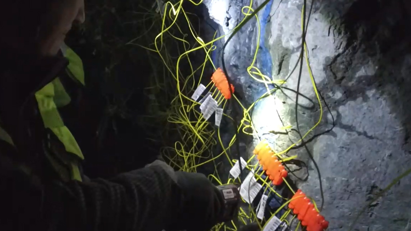
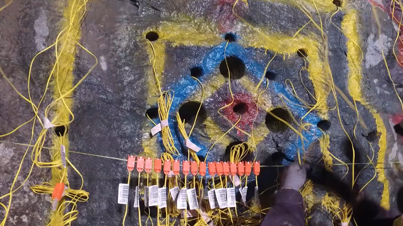
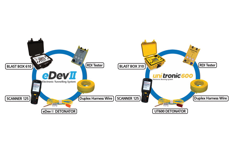
The electronic detonator incorporated by our company for the first time domestically is controlled by the most advanced electronic chip and has excellent time precision at 1ms (1/1,000sec), to enable a marked reduction in blasting vibration and noise.The Next Generation products, eDevTMⅡ and UniTronic TM600, are the most advanced electronic blasting systems, allowing control of blasting pollution through realization of high precision and unlimited stepped pulley effects, as well as immediate confirmation of detonator communication states of all without evacuation of manpower and equipment through the RDI Tester, so that operation stability and constructability have been dramatically improved in this next-generation blasting system.
Structural characteristics
More outstanding safety
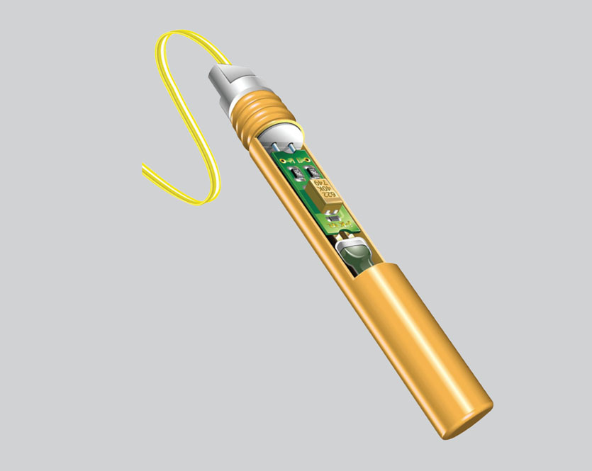
· Provides outstanding safety for external electric energy, such as thunderstroke, via an internal safety device· Provides safe test functions in the field via dual voltage (test, blasting) operation
More outstanding reliability
· Reliability of products improved by joint design of ASIC and PCB boards with US aerospace industry· Defects in assembly processes removed by use of PCB boards produced by advance assembly
· Defective parts removed in advance through advanced automated stress tests for PCB boards
· Reliability of 2-way communication improved by 5-time reinforcement of communication signals between detonator and system
· Possibility of overlapping IDs removed by use of extensive inherent detonator IDs
Effects & Advantages
eDevTMⅡ and UniTronic TM600 electronic blasting systems have more than 1,000 times of time difference precision (0.01%) compared with electric and non-electric detonators so that resolution capability of vibration between blast holes is excellent and ultraprecision vibration-controlled blasting operations can be performed in accurate compliance with the maximum charge per hang fire designed in advance.Electronic detonators time difference is controlled freely by units of 1ms (1/1,000sec), and safe and effective blasting operations can be performed without any reduction in blasting scale under diversified blasting conditions such as downtown tunnel construction, vertical hole construction, or bed excavation construction, etc. due to unlimited detonation stepped pulley and MS blasting effects.
Through 2-way communication between the RDI Tester and each detonator, and without requiring evacuation of manpower and equipment, it applies a system by which operation errors such as manufacturing defects in detonators and wire connection omission, etc. are reported beforehand to increase operation speeds, blasting analysis is easily achieved by automatic recording of time difference and inherent Nos. (barcodes) of all detonators after blasting operation, and tracking is possible upon loss of detonators.
Since the final blasting operation is performed after charging of the energy required for detonation in the internal battery, the electronic detonator is safe from any cut-off phenomena (whereby the detonator and explosive remain within the bedrock due to tube cutting of the leg wire for the electronic detonator or of non-electronic detonator) and enables free change of time differences even after loading within the blasting hole, to enable reliable blasting operation.
To prevent against the risk of external electric accidents such as leakage of current or thunder stroke, etc. a 2-stage safety device inside the detonator actively responds, and the final command for blasting is realized only by particular digital signals rather than general electric energy, making it the safest detonator.
Blasting System
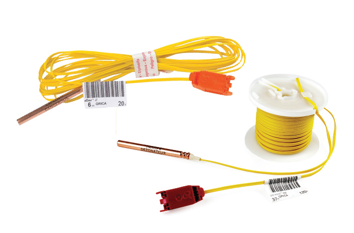
eDevTMⅡ/UnitronicTM600
· An electronic detonator which allows arbitrary time difference programming
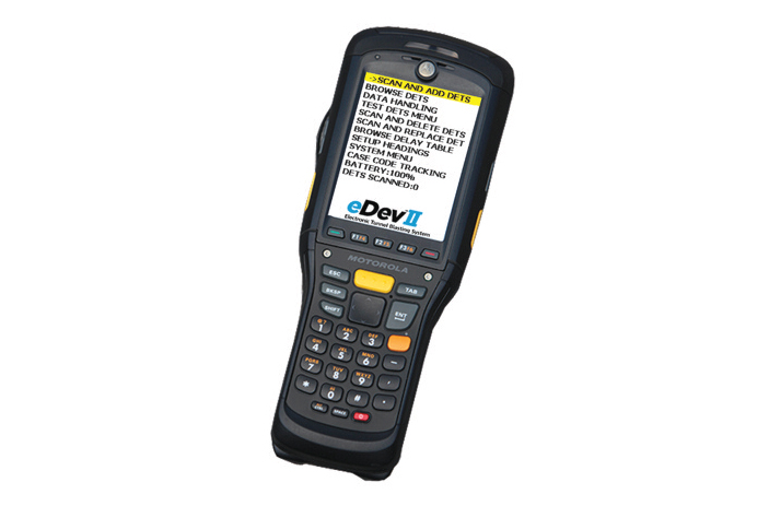
Scanner 125
· Assignment of time difference by scanning of detonator ID
· Maximization of operation efficiency (for tunnels) by grouped setting method for time differences of number delay concept
· Maximization of operation efficiency (for tunnels) by grouped setting method for time differences of number delay concept
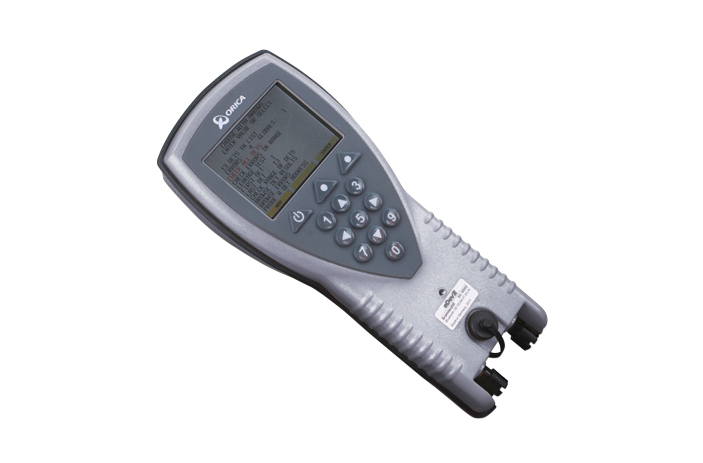
Scanner 200/260
· Same function as Scanner 125
· Function integration for Scanner and RDI Tester
· Function integration for Scanner and RDI Tester
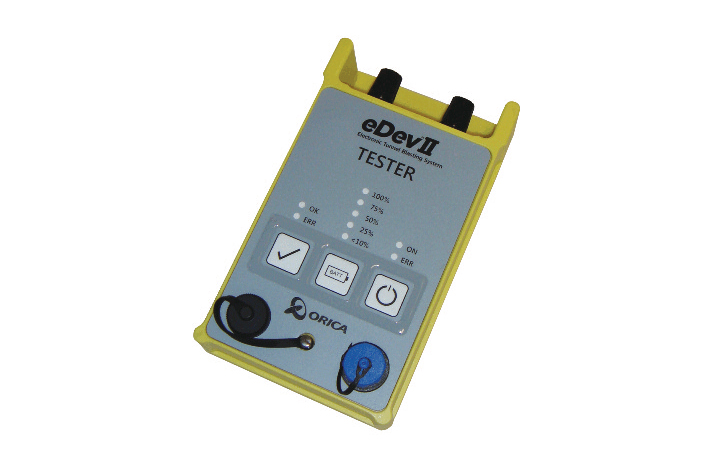
RDI Tester
· Confirmed 2-way communication in the blasting field
· Communication defects (wire connection error), undesignated time difference in the detonator, wire disconnection and shorting, amount of current leakage, as well as detonator defects checked
· Communication defects (wire connection error), undesignated time difference in the detonator, wire disconnection and shorting, amount of current leakage, as well as detonator defects checked
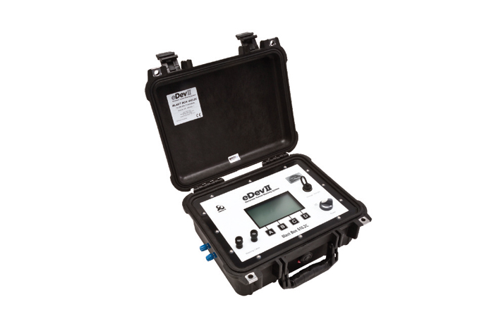
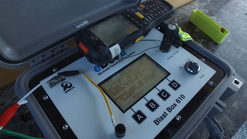
BlastBox 310 / 610
· 2-way communication with each detonator and blast
· Abnormality status in communication with each detonator checked beforehand
· Abnormality status in communication with each detonator checked beforehand
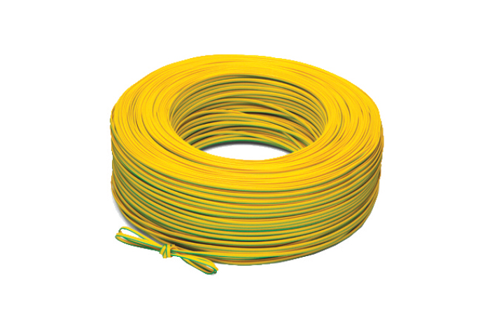
Duplex Harness Wire
· Auxiliary parent cable dedicated to electronic detonator providing convenient connection workability
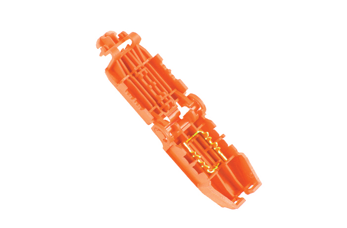
New Connector
· Connector allowing accurate and prompt wire connection
· Connection between detonator and Harness Wire
· Connection between detonator and Harness Wire
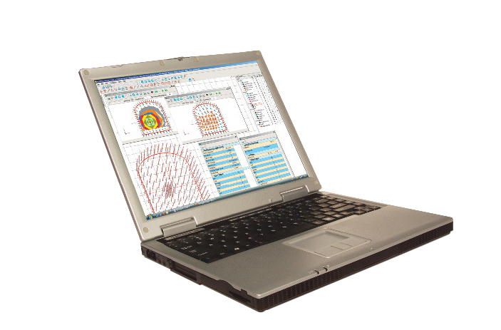
SHOT Plus T2
· Tunnel blasting design program
· Blasting vibration analysis and modeling
· Blasting vibration analysis and modeling
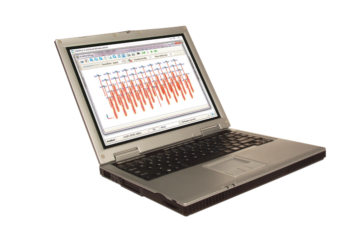
SHOT Plus 5
· Open air blasting design program
· Blasting vibration analysis and modeling
· Blasting vibration analysis and modeling
Blasting sequence
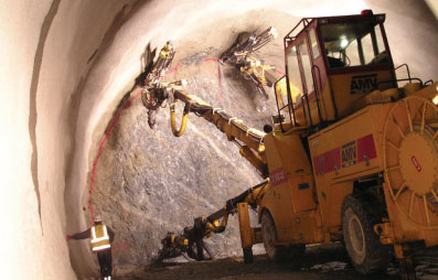
1.Boring
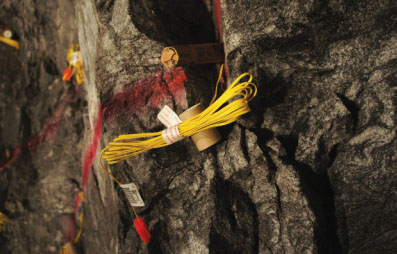
2.Charging
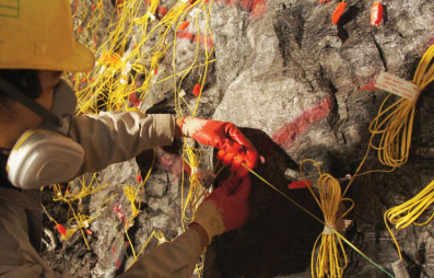
3.Detonator wiring
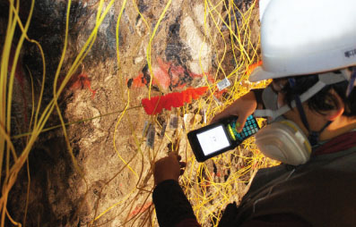
4.Scanning
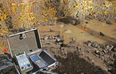
5.RDI Test
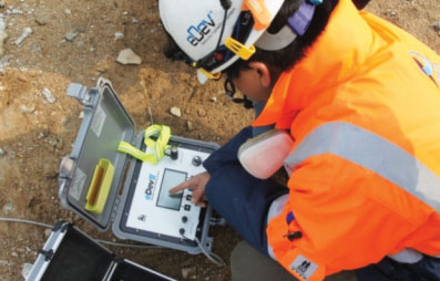
6.Communication / Blasting
Specifications
| Name |  |
 |
| Uses | for Tunnels | for River |
| Leg wire | Iron (copper coating) | Iron (copper coating) |
| Standard length | 6m | 6m |
| The tensile strength | 20kgf | 20kgf |
| Based charge | PETN | PETN |
| Time difference range | Minimum = 0ms Maximum = 20,000ms |
Minimum = 0ms Maximum = 10,000ms |
| 1Available per blasting detonator | 800pcs | 800pcs(Single Blast Box) 1,600pcs(2 in Synchro) |
| Quantity per box | 80pcs/Box(Length 6m) | 80pcs/Box(Length 6m) |
Molded explosive- HAKO
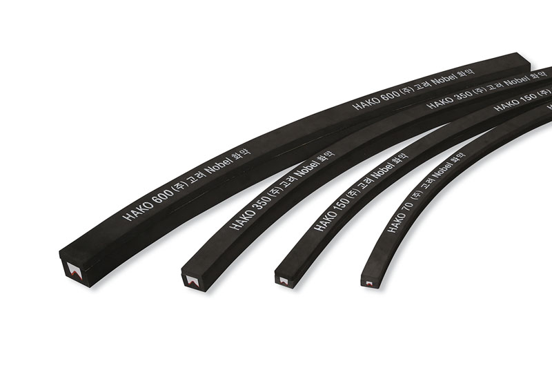
Features
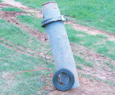
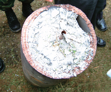
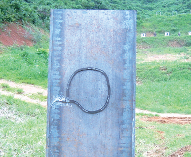
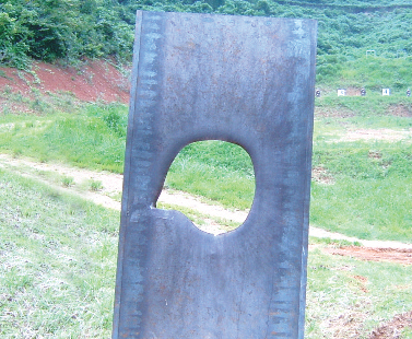
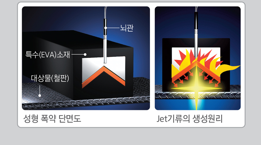
HAKO is a special explosive using the Neumann Effect, whereby a rectangular-shaped liner is destroyed in the lower part, and fine particles of metal are released to form a jet stream of about 10,000m/s, which collides with the target object for cutting.Suitable products should be used according to the object material and thickness. It is a molded explosive for special purposes in which only a limited part is cut off by concentrating the explosive power in the center such as the dismantling of iron structures, dismantling of military explosives, transmission or reception towers, and path pioneering.
Specifications
| Type | Dimension(mm) (L x W x H) |
Cutting thickness (mm) |
|
HAKO 70 |
2,000 × 30 × 20 | 3 |
|
HAKO 150 |
2,000 × 35 × 25 | 6 |
|
HAKO 350 |
2,000 × 40 × 35 | 10 |
|
HAKO 600 |
2,000 × 55 × 50 | 15 |
Principle of explosion cutting
Detonating Cord
Features
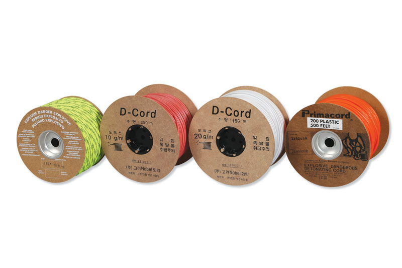
Detonating fuses are used for various controlled blasts (outermost blasting of tunnels, stone blasting, and quarrying, etc.), and used for other detonations under special conditions not allowing the use of electric detonators, as well as for explosive substitutes.Specifications
| Detonating Cord | Dimension |
Uses |
| 5g/m | 300(m/Roll) × 4(Roll/Box) | For signal transmission |
| 10g/m | 250(m/Roll) × 2(Roll/Box) | For controlled quarry blasting |
| 20g/m | 150(m/Roll) × 2(Roll/Box) | |
| 40g/m | 100(m/Roll) × 2(Roll/Box) |
